
by Alex Huckstepp
Effectively implementing 3D printing in a production environment requires software tools for design, simulation, pre-processing, distribution, manufacturing, inspection, and quality. Printer manufacturers (OEMs) provide software with their printers, but it often does not include all the functionality necessary for industrial scale additive manufacturing (AM). This post covers the different categories of 3D printing software, how they fit together in an AM workflow, and the leading companies providing commercially available solutions.
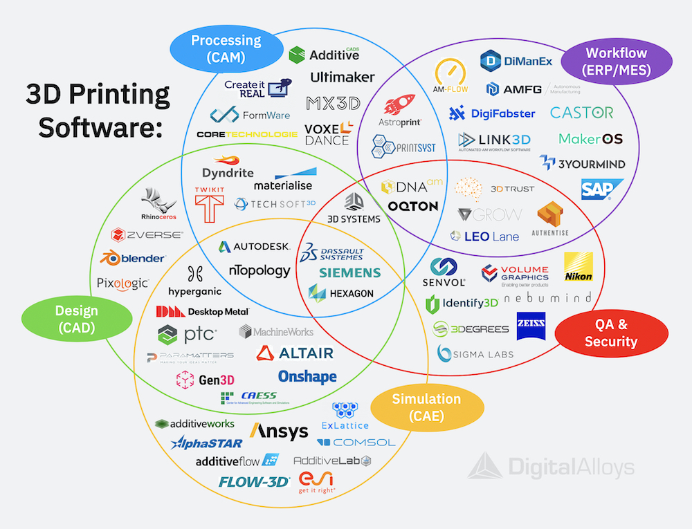
The 3D printing software workflow starts with design and ends with final quality approval. In between are many (not always consecutive) steps including simulation, processing, printing, inspection, and data analysis. The diagram directly above highlights the major categories of software tools used along the 3D printing working flow. We will examine them one at a time.
Design (CAD)
Computer-aided design (CAD) software is used by engineers and designers to digitally define a part’s 3-dimensional geometry. In most cases, the CAD software used to design parts for 3D printing is the same used for conventional manufacturing. Companies which produce CAD software include Dassault Systemes, Siemens, PTC, and Autodesk. For certain applications, AM specific design software is used to generate surfaces and structures which are optimized for 3D printing. Examples of such geometries include complex lattices, hollow features, and digital textures. Some of the companies which produce AM focused CAD tools are Materialise, nTopology, and Zverse.
There is a special class of design software referred to as “generative design” or “topology optimization” (GD/TO) which optimizes part geometry to achieve a desired performance given a defined loading scenario, boundary conditions, and design constraints. This software relies upon iterative computer simulations to refine the part geometry, combining CAD design rules with simulations from computer-aided engineering (CAE) tools. Leading providers of GD/TO software include Altair, Autodesk, and Paramatters.
Computer-aided manufacturing (CAM) is the use of software to control manufacturing equipment such as machine tools. CAM software takes CAD and CAE data as inputs and creates machine instructions (g-code) which program manufacturing equipment to perform an exact process. When “setting up a build” in CAM software, there are five key steps involved:
Determine Part Orientation:
The best way to orient a part within the build depends on a variety of factors such as accuracy and surface finish requirements, process physics, support structures, and optimal nesting (see below). CAM can suggest optimal orientations but usually requires user input.
Support Generation
There are many different approaches to supporting a part. The optimal support structure depends on its geometry, the process, material, and other variables. This step is largely automated in most CAM software.
Near-net-shape
Expansion:
For near-net-shape processes and applications, additional material (“stock”) is often defined in CAM to be added to surfaces with high surface finish and accuracy requirements. The stock material is removed through post-processes like machining.
Nesting:
Some 3D printing processes can accommodate printing many parts at once, distributed across the print plate and even stacked in the z-axis. CAM software helps to nest parts in order to maximize the number of parts per build without sacrificing the quality which is impacted by the build layout.
Slicing and Toolpath Generation:
Once all the above steps are complete and any custom print parameters selected, CAM software generates g-code which is sent to the printer to perform the printing process.

Follow Us!